Do I really need that much equipment? obviously yes.
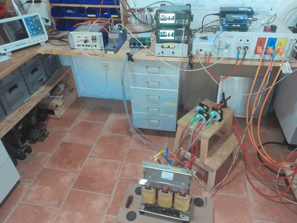
With this setup, I can measure the group delay of the analog inputs for the voltage and current measurement of the rotabench 6P inverter.
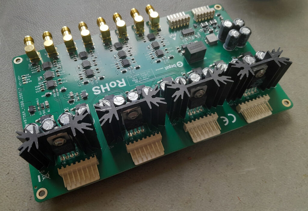
The calibration process has two steps: in the first step, the outputs of a simulated PMSM are fed into the inverter. The device “thinks” it is driving a motor. The signals are generated by two Siglent Arbitrary Waveform generators, which are fed into a signal conditioning and amplifier PCB. The amplifier simulates the current output of the current sensors. A FPGA is used to simulate the encoder signals. With the known outputs of the signal generator the phase delay of the inverter measurement can be determined and compensated.
In the second step, I use a big choke to generate some currents around 100 A RMS. These currents are measured with a cRIO, a signal conditioning and amplifier device and Signaltec CT200 current sensors. With these data the D- and Q- currents are calculated, which can be compared with the inverter setpoint. As the first step does not use real currents and the current sensors of the inverter, some adjustmens for the group delay of the current sensors is necessary.
When anything is running smoothly, I can achieve a phase accuracy < 1° (electric) on a (simulated) PMSM with 4 pole pairs, running at 1000 Hz (electrical) frequency.