… a lightweight Ethernet to RS485 and CAN Converter
With the end of support for Windows 10 there came a difficult decision for me: upgrade all test bench + device control PCs to Windows 11, or leave them on Windows 10? I decided against the upgrade. It would have meant to spend money and lots of work/time to re-establish the status-quo ante, just to get the prior functionality back. Instead I followed the advice “never change a running system”, created a 2nd network without internet access for lab-use only and migrated most of the rarely used control machines into virtual machines.
While Hyper-V on Windows 11 is a convenient approach, it has a major drawback: no USB pass-through. The official statement from MS, why there is no USB pass-through, is due to security reasons. Well, yea, sure …
This means I can not use my USB-devices, like my NI USB-RS485 or NI USB-CAN adapters on a Hyper-V virtual machine, when my software needs eg. RS485 communication or a CAN Bus. As my software was written for Windows, I had to stick to it, and I needed a simple approach to give my software its hardware capabilities back. Porting all this software to Linux would cost me years, so that’s not an option. So I built this:
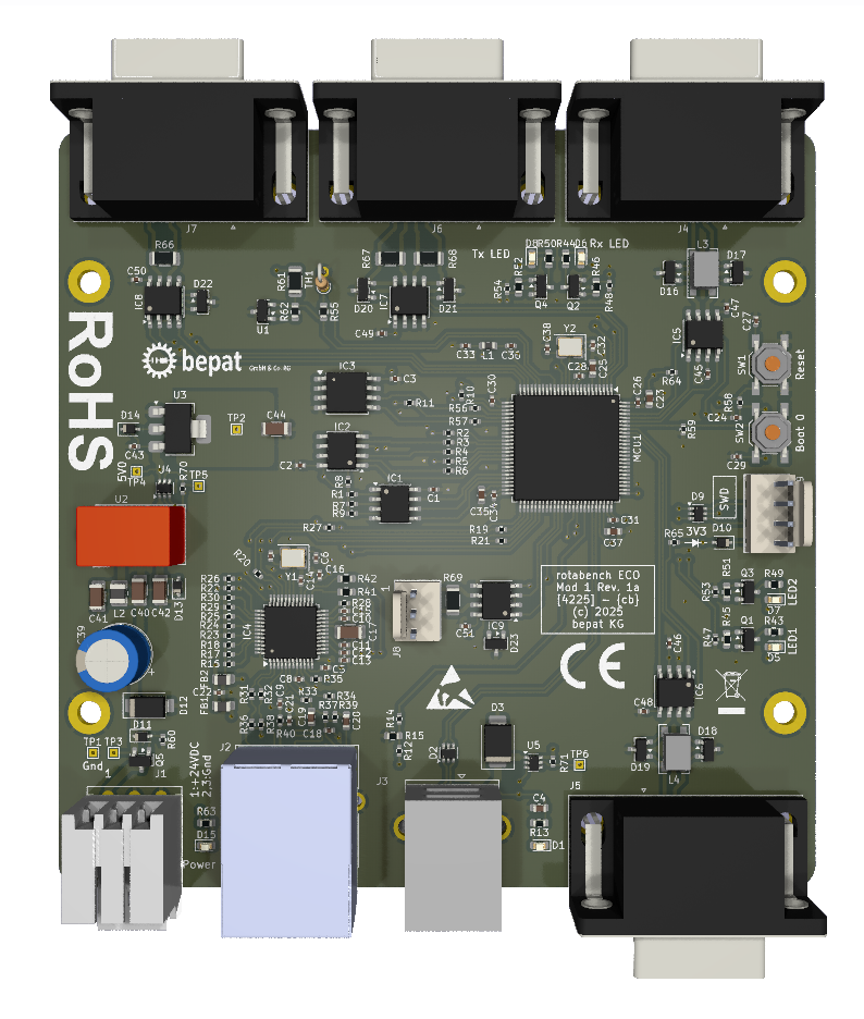
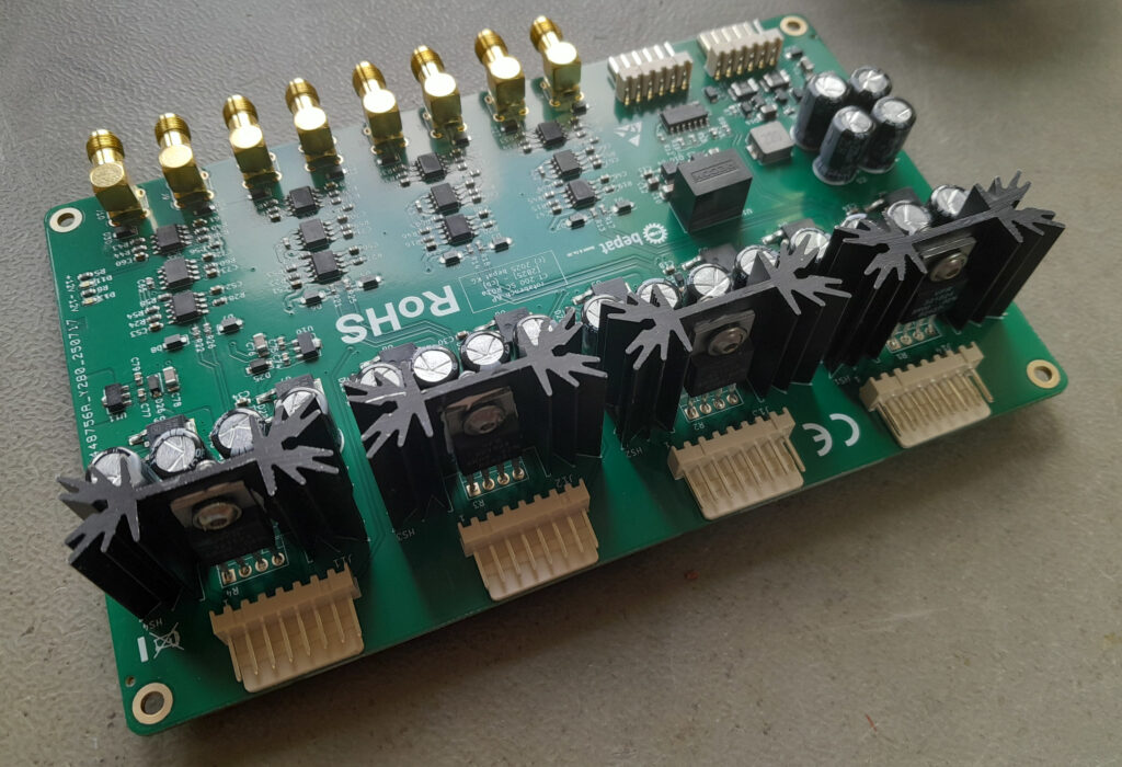
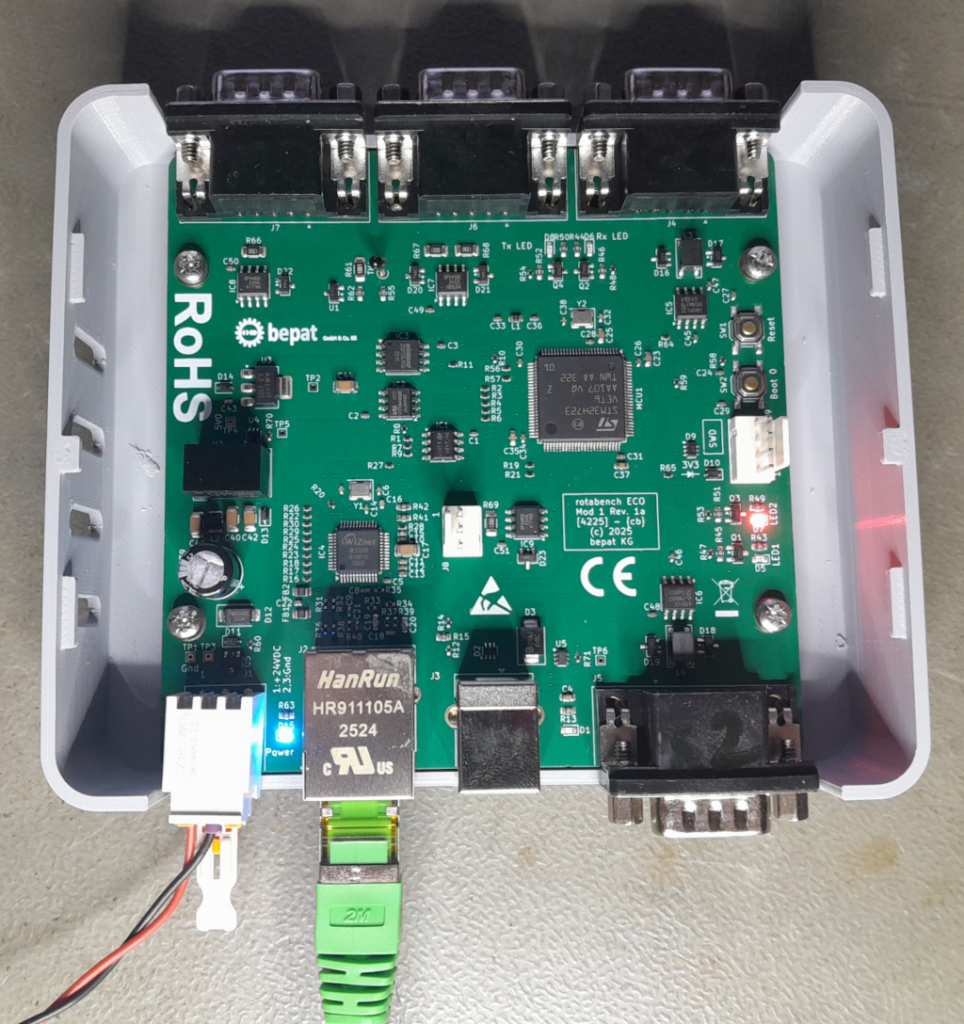
An Ethernet & USB to RS485 Half Duplex and RS485 Full Duplex Converter, with 2 CAN Ports, based on an STM32H7 MCU. And as I could, I made the device driver-less. The TCP-IP Protocol is the “driver”. And because there were still pins free on the MCU after all the mandatory elements were placed, I gave it 8 MB QSPI-SRAM – just in case.
Full Feature List:
– RS485 Half Duplex Port
– RS485 Full Duplex Port
– 2 CAN Ports – CAN-FD (5 Mbit/s) capable but not yet implemented in the Firmware
– 10/100 Mbit Ethernet
– USB for configuration
– 8 MB QSPI SRAM, 16 MB Flash Memory, 8 kb EEPROM
– STM32H723 MCU @ 550 MHz
On the software side, I simply have to add the communication library to my software and re-route the communication over Ethernet, instead of using the drivers like NI-Serial. This also means the device is implicitly cross-platform, as the protocol is the same on every platform.