When you build test benches for electric motors, you’re not just connecting wires. You’re orchestrating a complex symphony of high-current power, deterministic software, and mechanical precision. Over the last 20+ years, I’ve learned that the best way to ensure this symphony doesn’t hit a sour note is to eliminate the “walls” between departments.
The “5-in-1” Engineering Advantage
In large corporations, a single test bench project might pass through five different departments. Information gets lost, responsibilities are shifted, and the “Core” of the project loses its focus.
Since 2002, I have taken a different path. I handle the entire technological stack myself—not because I have to, but because it’s the only way to guarantee the level of quality my clients expect for their rotabench systems.
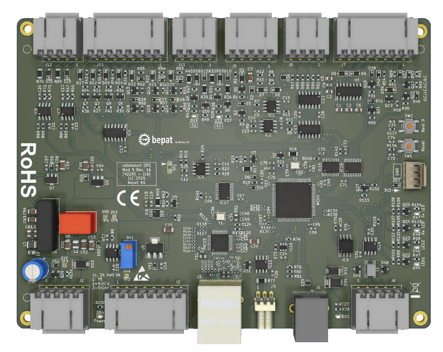
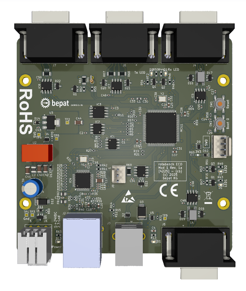
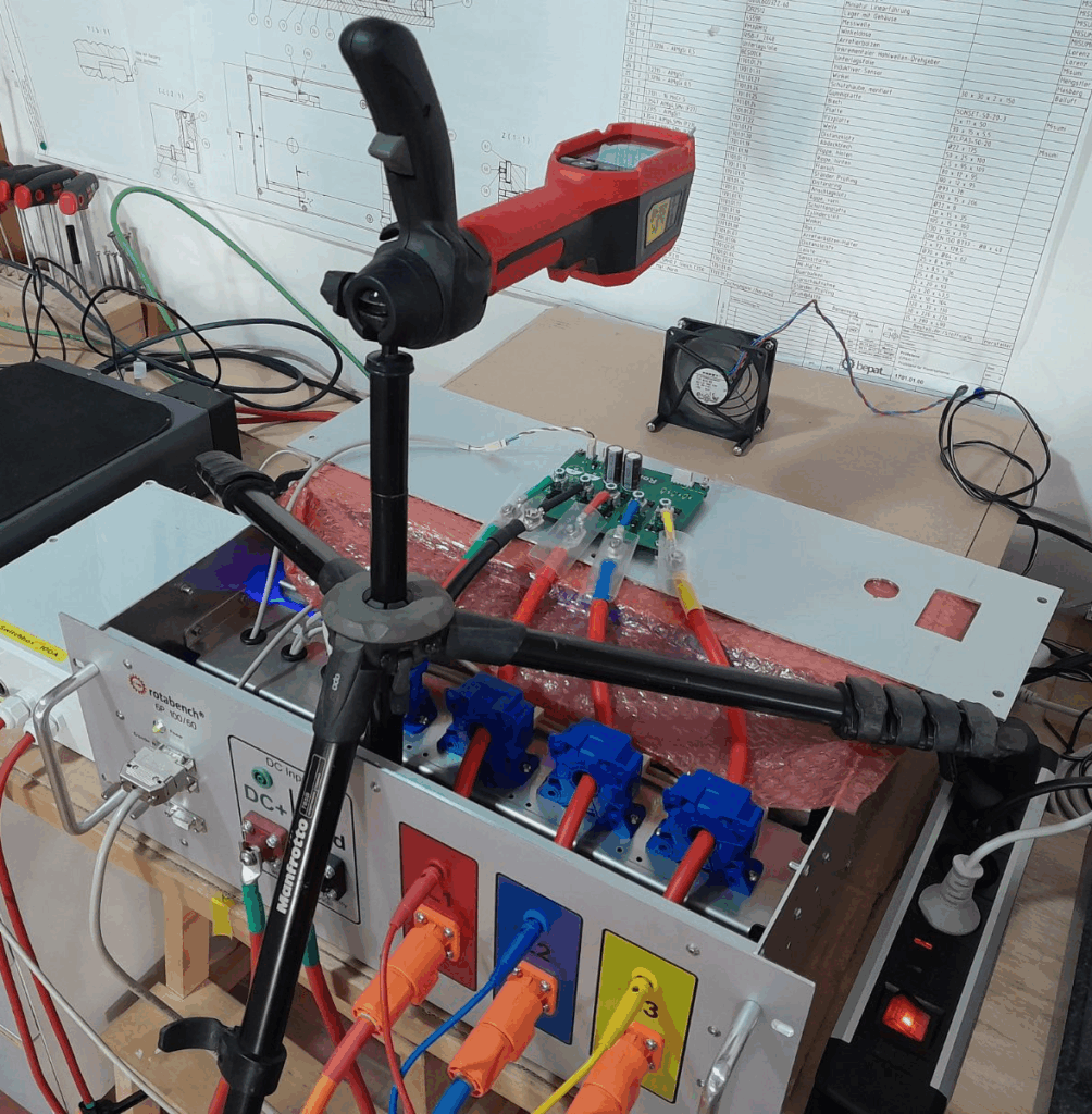
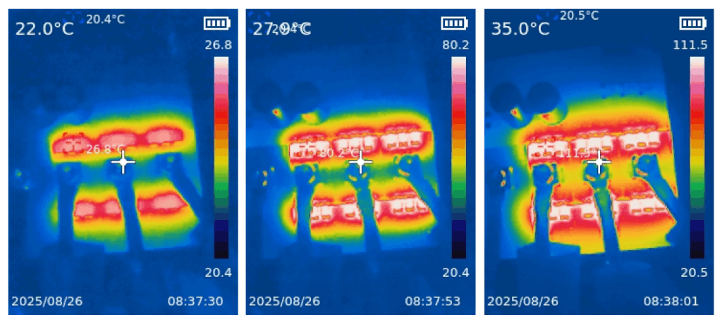
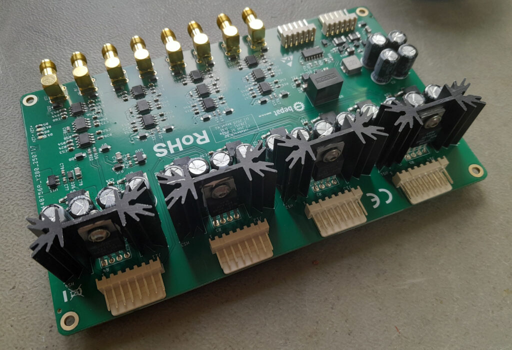
- Power Electronics & EDA: I design the PCBs for high-current applications up to 150A AC. Because I draw the traces myself, I know exactly how the hardware will behave under load.
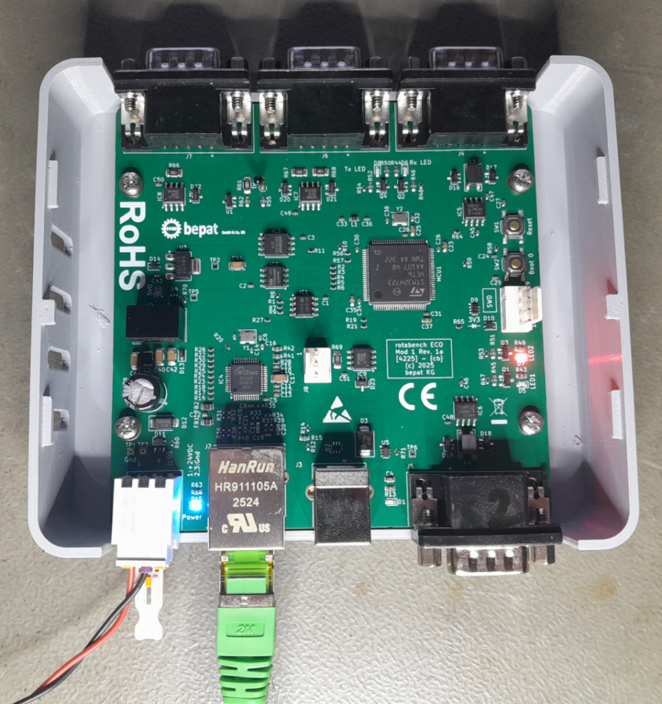
- Embedded Software Architecture: I write the C-code for the microcontrollers from scratch—no bloated libraries, just high-performance, deterministic execution (including custom AES-256 encryption for secure firmware updates).
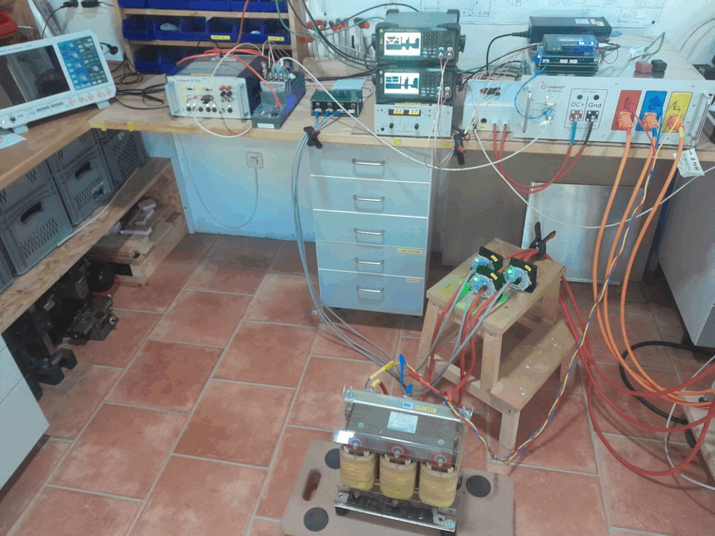
- System Integration: As a (former – 2007) certified LabVIEW Architect, I bridge the gap between low-level hardware and high-level user interfaces, creating a seamless data flow from the sensor to the report.
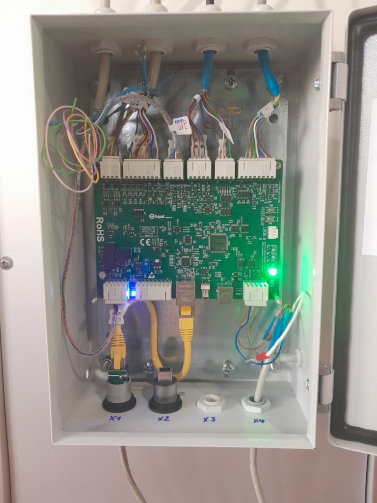
- Mechanical Construction: I design the physical housing and fixtures. Knowing exactly where a solder joint sits or how a high-current cable must be routed changes how you approach mechanical design.
Ownership Down to the Last Detail
Running my own company means I am the CEO, the Lead Architect, the Sales Guy, and—quite literally—the cleaning crew. If you visit my lab, you’ll find it spotless because I vacuum it myself.
Why does this matter to you? Because this level of “Ownership” is baked into every product I ship. If I’m willing to personally ensure my workspace is clean, imagine the level of care I put into your 50kHz control loop or your safety-critical shutdown logic.
No Middleware. No Excuses.
When you work with me, you’re talking directly to the guy who designed the circuit, wrote the code, and tested the 150A power stage. There are no “project managers” to translate your requirements into something the engineers don’t understand.
Just hardcore engineering, 20+ years of experience, and a deep respect for the physics of electric motors.