Stop Solving Integration Problems – Start Delivering Solved Problems

The Engineering Reality

In the last 20 years I was building test benches, I often had to spend way too much time for my taste with low-level integration of test bench components. The lesson I learned was: you don’t get paid for solving problems, you get paid for solved problems! If that sounds like a stupid marketing claim to you, just ask yourself: does your customer pay you if you spend hundreds of hours to work on a problem you could not solve? Most probably not. Your customer expects you to deliver a working solution, not a bucket full of unsolved issues.

Lesson #2: When you encounter technical issues—especially with low-level integration—it will always use more resources to solve them than you’d like. Your best and most efficient option is to mitigate such potential issues and use a solution you can buy on the market.

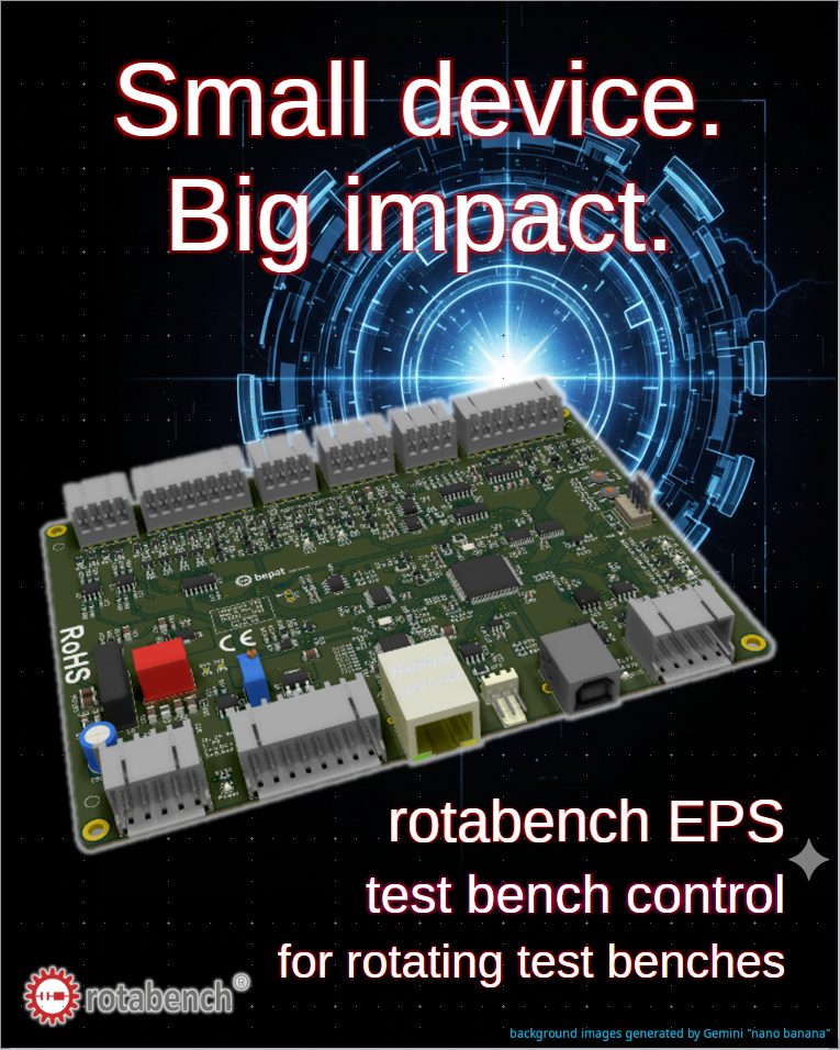
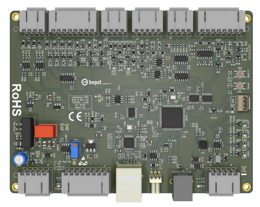
This is why I created rotabench EPS: it lets me (and you) leapfrog over most of the low-level integration issues and focus on functionality instead.

The following clip shows the startup sequence of a system where the “low-level heavy lifting” is already done. It’s about getting to the point where you can actually do your job—testing.

Why this matters for your workflow:

  • Risk Mitigation: By using a pre-integrated stack, you eliminate the “unknown unknowns” of hardware communication.
  • Resource Allocation: Stop wasting senior engineering hours on driver conflicts or bus timing.
  • Predictable Timelines: A deterministic startup means a predictable project schedule.

The Fast Track to Professional Test Bench Integration

Building a rotating test bench from scratch is a high-risk investment of engineering hours. Often, the “Entry-Level Burdens” of low-level hardware integration consume the majority of your project budget before the first measurement is even taken. With the rotabench® EPS Mod. 5, we are changing the game for system integrators.

The Challenge: Bridging the “Low-Level” Gap

rotating test bench with rotabench EPS test bench control system

The major challenge in system integration is bridging the gap between tedious hardware-level tasks and high-level application functionality. A standard test bench requires at least an industrial drive, torque sensors, safety controllers, and an automation PC. The time spent programming inverters or debugging sensor signals is time lost for developing your unique application logic.

The Solution: rotabench® EPS as your Unified Link

rotabench EPS as abstraction layer

The rotabench® EPS acts as an intelligent link between your high-level application and the physical hardware. It provides a pre-engineered core that standardizes the interaction between all components.

  • Drive Control: Direct speed or torque control without the need for deep-level inverter programming.
  • Torque & Speed: 1:1 plug-in for professional sensors (e.g., Kistler 4503) with integrated high-speed signal processing.
  • Integrated Safety: Built-in interface to bridge the emergency stop circuit between hardware and software.
  • Clean Interface: All data is pre-processed and delivered via one single TCP/IP or CAN interface.

Infinite Markets – One Core

Anything that rotates needs to be tested. The rotabench® EPS is the foundation that grows with your needs across various industries:

Automotive & E-MobilityHome & ProfessionalIndustrial & Green Tech
E-Bike & Micro-DrivesBattery Power ToolsHeat Pump Compressors
Chassis Actuators (EPS)Garden TechWind Energy Components
Active SuspensionPersonal CareConveyor & AGV Drives

Scalability Without Limits

We designed the rotabench® EPS to be the beginning, not the end. It makes complex hardware as easy to handle as a digital multimeter with an Ethernet port.

  • Software that Scales: Start with the included Basic Edition for commissioning and upgrade to the Professional Suite for full automation
  • Open for your Code: Seamless integration into your own LabVIEW, Python, or C# environments via Open API.
  • Form Factors: Available as a barebone PCB, in a DIN-rail housing (Plastic/Metal), or as a 19″ rack insert.

Small Device – big impact

From 19’’ racks to a single PCB: Streamlining Dyno Test Benches with the rotabench EPS.

rotabench EPS promo flyer page 1

I am not a marketing guy, I am an engineer trying to show the world the solutions I created. So please forgive me if this is not the perfect marketing pitch. On the other hand I can guarantee that my products are way better than my marketing 😉 … What I want to show you today is my new product: the rotabench EPS:

It is a test bench control PCB designed to combine and control all four major components of a dyno test bench — drive, torque sensor, encoder, and safety circuit — into one easy-to-use abstraction layer. Actually, it isn’t so new at all; the first versions go back to 2020. However, they were never intended as standard solutions for a wider market, but rather as custom builds for specific projects.

The main driver behind this project was my need for an extension board for my rotabench 6P lab-inverter for low-voltage electric motors. Without an active dyno test bench to brake the DUT (Device Under Test), an inverter is relatively useless. You can speed up the DUT and measure its idle behavior… yay, great. Not.

You need braking force to generate torque. Under these conditions, it’s a huge advantage if the inverter can also control the test bench hardware. It makes it much easier to measure, for example, characteristic curves when one device controls both engines: the drive and the DUT.

Since I built it myself, I designed it to be as convenient and efficient as possible:

  • TCP/IP Communication: I love it. You can use a $40 switch and a bunch of $5 cables to connect a complete test bench system to your control PC. With 10/100 Mbit Ethernet on the PCB, you can transfer more data than you’d typically need (the rtb EPS supports 5 kHz data streams).
  • CAN Bus: For situations where TCP/IP is overkill, I added CAN. It’s fast enough for up to 100 Hz streaming. Since coding low-level drivers isn’t the most exciting task, I kept the command footprint small: 10 commands are enough to start/stop drives, send setpoints, and query configurations, etc …
  • Integrated Signal Conditioning: I added the signal conditioning directly to the PCB. No external 19’’ racks filled with relays and connectors are necessary. It’s a simple wire from A to B.
  • WAGO 2091 Connectors: After crawling through confined spaces and ruining enough fingernails and screw heads, I chose push-in cage-clamp connectors. You can configure the wiring, click it in, and easily change it if needed.

The software for startup and maintenance (rotabench EPS basic) is included, featuring automatic speed and analog IO calibration (supporting DMMs like the Keithley DMM6500). There is also a “manual control” panel for hardware testing. (More on the software in next week’s post!)

Last but not least: I support the “Right to Repair”. The SWD connector is exposed, so if you want to, you could even write and run your own firmware on the board.

rotabench EPS Mod. 5 PCB

After re-inventing the wheel one too many times, I finally decided to design a standardized component for test bench control. The result is the rotabench EPS Mod. 5 Revision 1b

rotabench EPS Mod. 5 test bench control PCB
  • Drive Control: 24V Digital / ±10V Analog
  • Sensor Support: Kistler 4503B (RS232)
  • Connectivity: Ethernet & CAN-Bus, USB for Maintainance
  • Power-Supply: 24 Volt DC
  • Connectors: Wago 2091 Cage-Clamp

This PCB is engineered to control industrial drives via 24V digital I/O and ±10V analog I/O. It features native support for Kistler 4503B torque sensors (including integrated encoders) via RS232, and provides both Ethernet and CAN interfaces for seamless connection to a test bench control software.

The main purpose of this device is to eliminate the engineering overhead of creating a custom hardware abstraction layer for every new project. Instead, it serves as a turn-key solution that provides all essential features out of the box. By moving away from bespoke setups, engineering teams can bypass the complexities of low-level integration and focus immediately on their core testing objectives.

rtb EPS Mod. 5 in the test bench control cabinet

And this is how it looks like: the rotabench EPS Mod. 5 PCB in a control cabinet on my electric motor test bench.

rotabench ECO Rev 01

… a lightweight Ethernet to RS485 and CAN Converter

With the end of support for Windows 10 there came a difficult decision for me: upgrade all test bench + device control PCs to Windows 11, or leave them on Windows 10? I decided against the upgrade. It would have meant to spend money and lots of work/time to re-establish the status-quo ante, just to get the prior functionality back. Instead I followed the advice “never change a running system”, created a 2nd network without internet access for lab-use only and migrated most of the rarely used control machines into virtual machines.

rotabench ECO Rev 01

While Hyper-V on Windows 11 is a convenient approach, it has a major drawback: no USB pass-through. The official statement from MS, why there is no USB pass-through, is due to security reasons. Well, yea, sure …

This means I can not use my USB-devices, like my NI USB-RS485 or NI USB-CAN adapters on a Hyper-V virtual machine, when my software needs eg. RS485 communication or a CAN Bus. As my software was written for Windows, I had to stick to it, and I needed a simple approach to give my software its hardware capabilities back. Porting all this software to Linux would cost me years, so that’s not an option. So I built this:

rotabench ECO R01a KiCAD screenshot
rotabench ECO R01a

An Ethernet & USB to RS485 Half Duplex and RS485 Full Duplex Converter, with 2 CAN Ports, based on an STM32H7 MCU. And as I could, I made the device driver-less. The TCP-IP Protocol is the “driver”. And because there were still pins free on the MCU after all the mandatory elements were placed, I gave it 8 MB QSPI-SRAM – just in case.

Full Feature List:

– RS485 Half Duplex Port
– RS485 Full Duplex Port
– 2 CAN Ports – CAN-FD (5 Mbit/s) capable but not yet implemented in the Firmware
– 10/100 Mbit Ethernet
– USB for configuration
– 8 MB QSPI SRAM, 16 MB Flash Memory, 8 kb EEPROM
– STM32H723 MCU @ 550 MHz

On the software side, I simply have to add the communication library to my software and re-route the communication over Ethernet, instead of using the drivers like NI-Serial. This also means the device is implicitly cross-platform, as the protocol is the same on every platform.

no AI was used in the engineering process. Only human brain cells were tortured.
no AI was used in the engineering process.