From 19’’ racks to a single PCB: Streamlining Dyno Test Benches with the rotabench EPS.
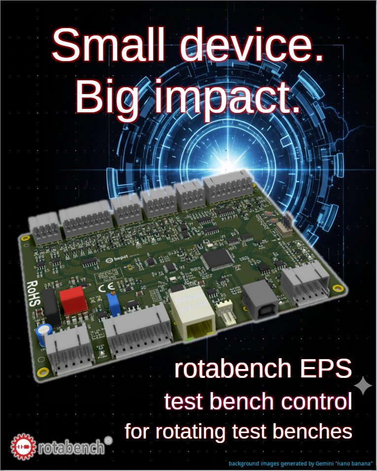
I am not a marketing guy, I am an engineer trying to show the world the solutions I created. So please forgive me if this is not the perfect marketing pitch. On the other hand I can guarantee that my products are way better than my marketing 😉 … What I want to show you today is my new product: the rotabench EPS:
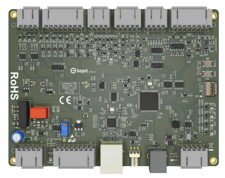
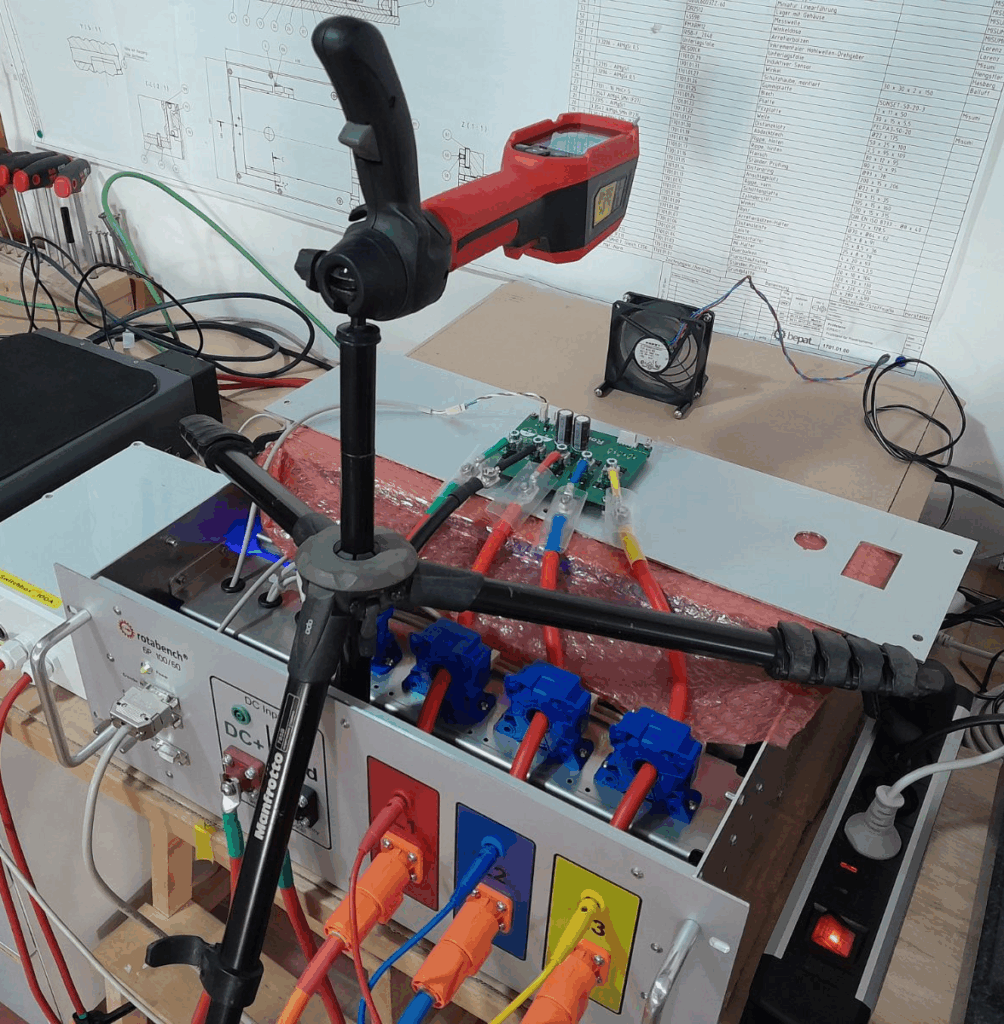
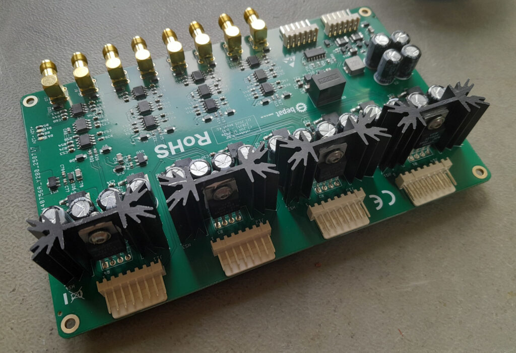
It is a test bench control PCB designed to combine and control all four major components of a dyno test bench — drive, torque sensor, encoder, and safety circuit — into one easy-to-use abstraction layer. Actually, it isn’t so new at all; the first versions go back to 2020. However, they were never intended as standard solutions for a wider market, but rather as custom builds for specific projects.
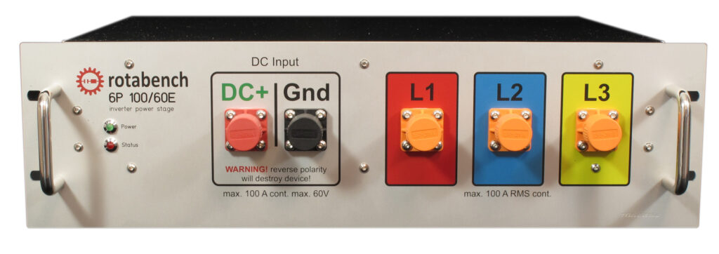
The main driver behind this project was my need for an extension board for my rotabench 6P lab-inverter for low-voltage electric motors. Without an active dyno test bench to brake the DUT (Device Under Test), an inverter is relatively useless. You can speed up the DUT and measure its idle behavior… yay, great. Not.
You need braking force to generate torque. Under these conditions, it’s a huge advantage if the inverter can also control the test bench hardware. It makes it much easier to measure, for example, characteristic curves when one device controls both engines: the drive and the DUT.
Since I built it myself, I designed it to be as convenient and efficient as possible:
- TCP/IP Communication: I love it. You can use a $40 switch and a bunch of $5 cables to connect a complete test bench system to your control PC. With 10/100 Mbit Ethernet on the PCB, you can transfer more data than you’d typically need (the rtb EPS supports 5 kHz data streams).
- CAN Bus: For situations where TCP/IP is overkill, I added CAN. It’s fast enough for up to 100 Hz streaming. Since coding low-level drivers isn’t the most exciting task, I kept the command footprint small: 10 commands are enough to start/stop drives, send setpoints, and query configurations, etc …
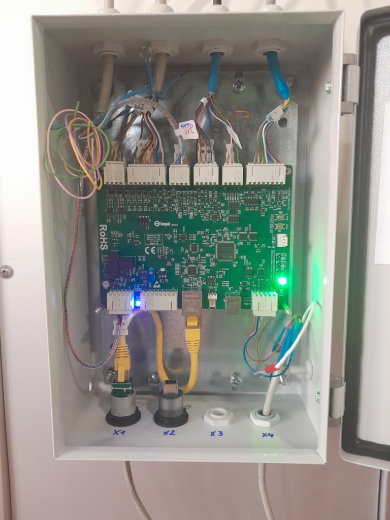
- Integrated Signal Conditioning: I added the signal conditioning directly to the PCB. No external 19’’ racks filled with relays and connectors are necessary. It’s a simple wire from A to B.
- WAGO 2091 Connectors: After crawling through confined spaces and ruining enough fingernails and screw heads, I chose push-in cage-clamp connectors. You can configure the wiring, click it in, and easily change it if needed.
The software for startup and maintenance (rotabench EPS basic) is included, featuring automatic speed and analog IO calibration (supporting DMMs like the Keithley DMM6500). There is also a “manual control” panel for hardware testing. (More on the software in next week’s post!)
Last but not least: I support the “Right to Repair”. The SWD connector is exposed, so if you want to, you could even write and run your own firmware on the board.